Search
Close this search box.

Planning High Quality Motion Paths for Robots, Workshop, Fall 2013

Software Workshop (sadna)

Autumn 2013-2014 (0368-3500-43)
Lecture: Wed 14-16, Kaplun 324
Instructor: Dan Halperin

Teaching Assistants: Kiril Solovey, Oren Salzman

Assistance with CGALEfi Fogel

Assistance with robots and camerasZim RamatiTom Shachar


General information

The aim of this workshop is to design, implement, and execute a system of a self-assembling puzzle. In particular, given a disassembled puzzle that consists of several pieces which are mounted on several pololu robots your task is to assemble the puzzle by moving the robots while avoiding collision between the robots and obstacles placed in the environment. The project consists of designing an algorithm, implementing a simulator, and executing the solution on real-life robots.

More details

The input of the problem consists of a description of polygonal puzzle pieces placed in some initial positions and an image of the assembled puzzle. The goal is to construct a series of movements of the robots that brings all the pieces to the target position.   As the task of assembly can be extremely challenging in some situations we impose that following restrictions to our puzzle:

  • Puzzle can be assembled using two hands.
  • Only one piece moves at a time.
  • Puzzle can be assembled in a monotone manner: there is a sequence of solution movements where each piece moves at most once.

Syllabus

In the beginning of the workshop, we will present you with relevant background material in a series of lectures:

  • Project presentation
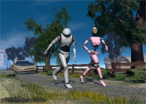
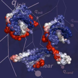
  • Introduction to motion planning, sampling-based motion planning and the MMS algorithm [slides]
  • CGAL and auxiliary code overview

Course Requirements

  • Programming abilities: The students are expected to program in C++. Familiarity with the language is an advantage but not required.
  • Teamwork: The project is intended to involve a significant amount of teamwork. Based on our experience over the years, the recommended team size is six students, where three students will be working on the simulation and the rest on the physical robots.
  • Course staff: Except for doing the project for you, we are here to help you with any question. Please do not hesitate to contact the course’s team.

Tentative Schedule (stay tuned!)

The project will proceed according to the following milestones:

23.10 Forming teams – You will submit (by email) a list of the group’s members, a group name, and the roles of the participants (simulation/physical robots/integration).

27.11 Planned project presentation – You will have a 15 minutes slot to present the project to us in class, followed by a discussion.4.12 Submission of final plan. Submit a detailed final project plan (by email), based on the initial plan, but this time we will expect more detailed solutions:
(i) Algorithmic details.
(ii) Milestones towards the final goal.
(iii) Tools that are going to help you program / run the project (libraries, programming languages, etc.).
(iv) Open questions, conflicts and so on.

1.1 Project “Proof of Concept” By this time, you will be required to show that the basic technical infrastructure of the project works.

  • The robot groups are required to be able to solve a simple puzzle that consists of two polygonal parts (which they will construct either from cardboard or by 3D printing). They should design the puzzle by specifying the start and target positions and send a query, that describes the problem, to the simulation group, which will return a solution to the problem. Then, the robot groups should be able to execute the solution.
  • The simulation group should be able to execute a simple assembly problem that consists of two parts, and produce smooth paths. Additionally, they should be able to cope with scenarios that involve several more robots.
  • Each group should choose a coordinator that will interact with the robot/simulation group. All groups should decide on a unified standard for communication, e.g., how should a path or scenario be represented.
  • Additionally, every group is required to present in the meeting a document that describes the tasks they are planning to complete for the prototype meeting.
27.2 Prototype At this point in time, we wish to see your initial development, in order to make sure you are working in the right direction. You will show us a basic prototype of the final project (as you committed to). The prototype is expected to be a relatively small part of the final project (it is not expected to be fully functional). However, it should give a very good feeling of where you’re heading. In addition, by this stage we will check that your code can integrate with ours for the league to run smoothly.
30.4 Submission. Submitting a fully functional project, including documented code, a detailed user guide and a developer guide .
(i) Developer guide – will include details about the algorithm, the implementation and the code design, to allow a new developer to approach your code.
(ii) User guide – should outline the purpose of your project and its usage in a clear manner.7.5 16:00 at Schreiber 309 Presentation Participation required.
The presentation will be public and will not be restricted to the participants of the workshop.
You should give a concise description of the methods. You will need to discuss the advantages and disadvantages of your implementation.

Simulation Section

CGAL warm-up: Download the C++ code and fill the blanks. You may need to generate a VSe solution to test your result. Don’t forget to set the correct paths, according to the CGAL installation guide (QT paths are not required in this specific exercise).

Robot Section

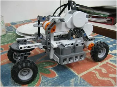
This year’s physical-robot projects will be based on Pololu 3pi robots, groups will be given up to 5 robots in 1-2 robots increments.

requirements:

  1. python2.7
  2. robo3pi a python library for controlling robots.
    1. a newer version which also introduces the method ‘rotate’ for servo movement can be found here.
  3. FTDI drivers for the USB dongle
    1. if you have problems with installing theses drivers try the Arduino IDE, which has a drivers library with full support.

3pi control

Added here is a python library to control your 3pi robots using serial wireless dongle (zigbee/bluetooth/UHF).

Unlike the first stage this gives you direct control over the robot allowing movement by selecting a speed for each wheel – now the timing factor is on you! make sure your robot is burned with the code for this kind of movement (displaying “Sadna  2.1” or greater on startup).

the speed can be any number x as long as -256<x<256 (notice the no ‘=’). 255 is 1m/s in either direction so calculate your timing.

example of use:

import robo3pi as s

import time
s.init(‘com11’) # this is the com the xbee dongle identified itself on my computer.
s.move(‘1’, 255, -117)
time.sleep(0.4)
s.addToGroup(‘1’, ‘G’)
s.addToGroup(‘2’, ‘G’)
s.stop(‘G’) # ok so robot #2 never started moving but this will control all the group.

Note that you should give the robot time between one command and the next to process.

Camera Tracker

Please download the tracker here.

The program will allow you to send the location of each polygon using UDP methods. and a written CSV log for debugging purposes.

THIS is a link to the instructions video showed at the beginning of the workshop.

3D Printing

Among other tasks, you will need to produce the puzzle pieces (subassemblies) either from cardboard or from plastic.

Recently, we have purchased a dual-head 3D printer from Something3D, a local company that manufactures 3D printers.
The printer is located in the ACG lab (Schreiber basement M-18).The printer supports three types of filaments:

  1. ABS
  2. PLA
  3. PVA is water soluble best used for support material, and probably not needed for this project.

Currently, the ABS filament is mounted on the the first nozzle. (We haven’t even ordered PVA yet).

If you decide to 3D-print the puzzle pieces (which is recommended), you will need to create digital models of the puzzle pieces to start with. A comprehensive list of modeling software tools can be found here. If you don’t have a preferable modeling tool, we recommend Sketchup Make.

Once you have a model, you will need to generate the “program” that consists of instructions to print it. Our 3D-printer (like most 3D printers) accepts programs written in G-Code. A G-Code program can be fed directly to the printer from a flash memory card.  The printer in the lab is also mounted on a computer. We have installed Repetier and Slic3r on this computer. These software tools are freewares, so you can install them on your private computer and use them to generate the necessary G-Code programs. You can come to the lab with the G-Code programs and a memory flash, and start a print job right away. Alternatively, you can come to the lab with the digital models, and use the computer, the printer is mounted on, to generate the G-Code programs, and then start a print job.

We don’t have much experience with the this new printer (or with any 3D-printer for that matter), but we will be happy to assist you as much as possible.
The website of Something3D contains a complete user manual of the printer.
Please, coordinate with us before you start your first print job.

Visit the 3D printing page for more information.


Reading Material

  • Barak Raveh, Angela Enosh, and Dan Halperin
    A Little More, a Lot Better: Improving Path Quality by a Path Merging Algorithm (H-Graphs)
    IEEE Transactions on Robotics, 27(2): 365-371, 2011 [link] ; arXiv [link]

Additional Reading Material

  • Chapter 7: Sampling-Based Algorithms in Principles of Robot Motion: Theory, Algorithms, and Implementations
    H. Choset, K.M. Lynch, S. Hutchinson, G. Kantor, W. Burgard, L.E. Kavraki, and S. Thrun, The MIT Press, 2005.
  • Chapter 5: Sampling-Based Motion Planning in Planning Algorithms,
    S.M. LaValle, Cambridge University Press, 2006
    Web version

Installing CGAL and related programs on Windows operating system

This page explains how to install CGAL 4.9 with Boost 1.59.0 and Qt5 5.7.1 on Windows 8 using Visual Studio 12 (2013) generating 64 bit binaries. The same procedure should apply to earlier versions of Windows.

Note that during the entire setup you need Internet connection!

Note that the installation requires significant disk space. Make sure to free enough disk space before the installation.

Instructions on adding Environment Variables in Windows are at the end.

DOWNLOADS:

IMPORTANT: make sure that you install everything in 64-bit.

  1. Visual Studio 12 Professional (recommended) or Express.
    Professional – Students can get a free version here
  2. Boost 1.59.0: here
  3. CMake 3.7.1
  4. CGAL 4.9.0
  5. Qt5 5.7.1
INSTALLATION:
In parentheses are the paths on my computer.
1) Visual C++ 2013:
  •  If you use the offline version, choose to install Visual C++.
  •  Accept the license terms.
  •  You may select a custom installation (instead of full) and select only Visual C++ (unselect other features).
  •  You don’t need to install “SQL Server” & “Silverlight Runtime” although you may.
  •  There is a chance that it is recommended to reboot now.
2) Boost

Versions earlier than 1.55 used to include a binary installer. Such an installer is no longer available. However, the procedure is fairly simple. There are several ways to build boost; the following is referred to as “build from source”.

  • Open a command-line terminal, such as ‘cmd’.
  • Make the compiler known by running the following batch file:
c:\Program Files (x86)\Microsoft Visual Studio 12.0\VC\bin\vcvars32.bat
  • Download the boost archive, unpack it to a target directory of your choice (e.g., C:\boost\boost_1_55_0), and change directory to target directory.
  • Run:
.\bootstrap
  • Then, build the static, shared, single and multi threaded boost libraries:
.\b2 link=static,shared threading=single,multi variant=debug,release
  • Make sure the subdirectory stage\lib\ has been populated with the compiled libraries (both .lib and .dll files).
3) CMake
  •  -Agree to the license.
  •  Check “Add CMake to the system PATH for all users”.
  • Check “create desktop icon”.
  •  Next, Next, Next.
  •  Finish
4) QT
  •  Agree to the license.
  •  Next, Next, Next, Install.
  •  Add QTDIR variable with the value C:\Qt\5.7.1 to the environment variables (if it’s not already there).
  •  Add <QT>\bin to the system PATH. (C:\Qt\5.7.1\bin)
4.1) QT Visual Studio 2013 addin:
  •  install the addin (Is it still necessary in VC 12?)
5) CGAL
  •  CGAL installation will need to connect to the internet for GMP and MPFR.
  •  Be amazed by the splash screen.
  •  Agree to the license.
  •  Just choose the default: with GMP and MPFR, and with examples and demos.
  •  64-bit (for me).
  •  In the “Setting Environment Variables” screen, choose all users and make sure that CGAL_DIR is checked.
  •  Install.
  •  Add <CGAL_DIR >\auxiliary\gmp\lib to the system PATH. (C:\Program Files\CGAL-4.9\auxiliary\gmp\lib)
Now you need to compile CGAL
  •  Open CMake – cmake-gui (on the Desktop) – if you are using win7 make sure you open the program in administrator mode – right click on the icon and click on “run as administrator”.
  •  For both “Where is the source code” and “Where to build the binaries” specify the CGAL Installation folder (C:\Program Files\CGAL-4.9)
  •  Click Configure.
  •  Choose “Visual Studio 12 2013” and click “Finish”
  •  Click Generate
  •  A solution named CGAL was created in the directory.
  •  Compile ALL_BUILD project both in Debug and Release (ignore the compilation error in CGAL_imageIO).
  •  All CGAL libraries should be under the lib directory.
6) Sanity check (optional)
  •  Open CMake (cmake-gui, can be found on the desktop) – (for win7 users, use “Run as admin”)
  •  Choose “Where is the source code:” to be the Triangulation_2 demo directory under the CGAL installation. Namely, <CGAL>/demo/Triangulation_2 (C:\Program Files\CGAL-4.9/demo/Triangulation_2).
  •  Choose “Where to build the binaries:” to the same directory.
  •  Click Configure
  •  Click Generate
  •  Go to the directory (C:\Program Files\CGAL-4.9) and open the solution and compile. Run the Delaunay_triangulation project for check (in debug and release)
7) Customizing env – If you are not using CMake to create new VS projects
 
 Note: the following operations should be repeated for the Debug and Release modes
  •  Right-click on the selected project and select “Properties”.
   Go to C/C++ -> General . Add the following to “Additional Include Directories” (include)
   * include: <Boost> (C:\Program Files\boost\boost_1_59)
   * include: <CGAL>\include (C:\Program Files\CGAL-4.9\include)
   * include: <CGAL>\auxiliary\gmp\include (C:\Program Files\CGAL-4.9\auxiliary\gmp\include)
   * include: <QT>\include\Qt (C:\Qt\5.7.1\include\Qt)
   * include: <QT>\include\QtCore (C:\Qt\5.7.1\include\QtCore)
   * include: <QT>\include\QtGui (C:\Qt\5.7.1\include\QtGui)
  Go to Linker -> General. Add the following to “Additional Dependencies” (include)
   * library: <CGAL>\lib (C:\Program Files\CGAL-4.9\lib)
   * library: <QT>\lib (C:\Qt\5.7.1\lib)
   * library: <Boost>\lib (C:\Program Files\boost\boost_1_59\lib)
   * library: <CGAL>\auxiliary\gmp\lib (C:\Program Files\CGAL-4.9\auxiliary\gmp\lib)
For a specific project using CGAL you need to ignore the auto-link of gmp and mpfr. The names below are for Debug.
 – Linker -> Input
   * Add libgmp-10.lib and libmpfr-4.lib to “Additional Dependencies”
   * Add gmp-vc100-mt-gd.lib and mpfr-vc100-mt-gd.lib to “Ignore Specific Library” (gmp-vc100-mt.lib and mpfr-vc100-mt.lib in release mode).
For a specific project using QT:
 – Linker -> Input
   * Add qtmaind.lib, QtGuid4.lib, and QtCored4.lib to “Additional Dependencies” (qtmain.lib;QtCore4.lib;QtGui4.lib in release).
Important: In case that the compilation succeeds but the linker is unable to find cgal-related dlls (“the program can’t start because cgal-vc100-mt-gd-4.2.dl is missing”)
find these files in the CGAL directory and copy them either to the system32 folder of windows, or the folder of the visual studio project.
Try to compile this programs:
Hello CGAL: http://www.cgal.org/Manual/latest/doc_html/cgal_manual/Introduction/Chapter_main.html

Setting up PATH variable or other Environment variables on windows systems

    1. From the desktop, right-click My Computer and click properties.
    2. (on Vista/Win7/Win8 click Advanced system settings on the left side)
    3. In the System Properties window, click on the Advanced tab.
    4. In the Advanced section, click the Environment Variables button.
    5. Finally, in the Environment Variables window, highlight the path variable in the Systems Variable section and click edit. Add or modify the path lines with the paths you wish the computer to access. Each different directory is separated with a semicolon as shown below.C:\Program Files;C:\Winnt;C:\Winnt\System32

LegoNXT Robot – ABS Motion Planning Project

 This work is part of a High quality Motion Planning Workshop (spring-2009).

Project Goal:

Generate a path from source to target locations while avoiding obstacles, optimized in some aspects, for our constructed robot to follow.

The project included:

  • Designing and constructing a robot based on Lego (TM) parts with the MindStorm controller.
  • Designing an algorithm that calculates an efficient path according to parameters entered by the user.
  • Creating A second algorithm that converts the output of the first algorithm to a set of instructions for our robot to follow.

Project Milestones

  • Construction – we have decided to construct our robot as a Car-like robot. I.e. Forward motion generated in the front and steering generated in the back. This decision stemmed from our desire to make the project more interesting, compared to common robot construction models. Retrospectively this was proven to be harder than we thought, due to unexplained misbehavior by the robot from time to time (inaccuracies while following instructions).
  • Optimization aspects were selected:
    • Clearance – maximum distance to obstacles
    • Distance – minimal path distance
    • Turns – preference for turns that the robot performs well
  • Implementation & Design
    • Development/Final Environment: Our development environment consisted of “Google Sketchup” for designing the problem to be solved, “OOPSMP” libraries for existing motion planning algorithms and framework, “Microsoft Visual Studio” for coding, and “Bram NXT” library for controlling the robot.
    • Motion planning: Our approach was to use existing algorithms for motion planning, and hybridize their solution paths to a single path optimized for the aspects we selected, while prioritizing these aspects using weights given by the user.
    • Translation to robot control: We decided to address the issue of control by regarding the solution path as a path to follow, rather than a description of the robot’s exact state at a given time (which is the broadly accepted convention).

Results

Video of our robot in action

Non holonomic motion planner project

Authors : Bosmat Eldar, Itamar Berger, Gal Zohar
This project is part of the high-quality motion paths for robots workshop, Spring 2009

Project Goal

Generating high-quality paths for non-holonomic robots.

In 2D worlds, finding a path from point A to point B is an interesting problem which can easily be solved. However, when there are limitations on the robot’s movement, the problem may become difficult. In this project we’ve tried to deal with the limitations of cars’ movement. Cars are non-holonomic, so actions such as parking or making a sharp turn are not always trivial. A typical GPS doesn’t take these limitations into account.

In order to make high quality paths, we’ve defined several criteria for path quality: length, smoothness, clearance and minimizing reverse and steering amount.

The resulting project

We’ve examined the solutions currently suggested for this problem over the net, and a particular article appeared to be a good start for our basic demands –  “Randomized Motion Planning for Car-like Robots with C-PRM” by Guang Song and Nancy M. Amato from Texas A&M University. [PDF]

The C-PRM algorithm provides us the ability to control the preferred paths procedure. We used its basic structure to achieve our quality criteria.

The results were encouraging, however, we thought the Hybrydization method we’d learned in the workshop might improve the path quality. Merging the methods wasn’t trivial. The combination of the paths required some creativity because the C-PRM algorithm wasn’t meant to support it.
This optimization improved the results in every quality measure, but, as expected,
solving the problem multiple times reqiured that much more time.

We noticed that custom optimizations can assist in specific situations,
so we’ve added some more optimizations for situations such as parking and narrow passage.

Finally , the resulting project is a fully GUI standalone application which contains a
“Scene Creator” – a painter program for creating 2d worlds ( and saving as XML files)
made from polygons, and the main program – an impressive non-holonomic motion planner.

Visual results

green: start point
red: end point

Implementation

The project was written in C++ with support of the following software packages:

  • OOPSMP – we used this package as a basic framework for our project.
    This package contains some useful tools such as Graph structures,
    Search Algorithms, State Sampler ,XML reader, basic GUI etc.
  • PQP – Collision Detector , assisted in finding collision and distance measurements between polygons.
  • Triangulate – used for triangulate the polygons for the collision detector.
  • QT – used for 2D GUI implementation.
  • OpenGL – used to draw the problem.

We’ve implemented and modified the C-PRM algorithm.

More Details regarding implantation can be found in our Developer Guide Manual.

Conclusions

We’ve learned a lot in this workshop. We’ve been introduced to the interesting field of MotionPlanning –
A broad field with much room for innovation.
In this project we were required to deal with a large software package and a lot of self learning.

We were given a great deal of freedom and support throughout the project.
We believe our final results are interesting and perhaps even innovative in the field of car motion planning.

Movie

Press here to watch the movie

Yair Oz - Webcreator

Contact

Skip to content